What is Thermal and Electrical Separating Pad in Metal Core PCB?
- Views
- 28 Jun 2024
Metal core PCBs are widely used in high-power applications requiring efficient heat dissipation and robust electrical performance. And in the metal core PCBs, there is a kind of PAD we called thermal separating PAD. This is a critical component in these boards, especially for thermoelectric separation technology. Do you know about it? In this article, we will introduce its meaning, functions, benefits, and applications of these separating pads in MCPCBs.
What is a Metal Core PCB Separating Pad?
A Thermal and Electrical Separating Pad is a type of pad designed on metal core PCB to separate the paths of heat and current. Its primary purpose is to optimize thermal management and electrical performance, which is crucial in electronic devices and circuits. The thermal and electric separating pad on PCB helps to manage heat effectively. Thereby enhancing the stability and performance of the circuit board. The main features and functions of thermal and electrical separating pads are as follows:

Thermal Management
Ø Heat Dissipation: Directs heat to specific areas or heatsinks, preventing heat accumulation around sensitive electronic components and avoiding overheating.
Ø Thermal Path Optimization: Rapidly transfers heat from the heat-generating components to the heat dissipation areas, reducing thermal resistance and improving cooling efficiency.
Electrical Performance Optimization
Ø Independent Current Paths: Ensures that the current path is not affected by the thermal path, avoiding resistance changes due to heat and ensuring stable electrical performance.
Ø Reduced Electrical Noise: Minimizes electrical noise interference caused by heat, enhancing signal quality.
Structural Design
Ø Physical Separation: Typically involves physically separating the thermal and electrical conduction paths in the design, possibly using different materials or geometric designs to achieve this.
Ø Material Selection: Uses materials with good thermal conductivity (such as copper or aluminum) for heat conduction, while the current path might use materials with better electrical conductivity, or even insulating materials for separation in some cases.
Application Scenarios
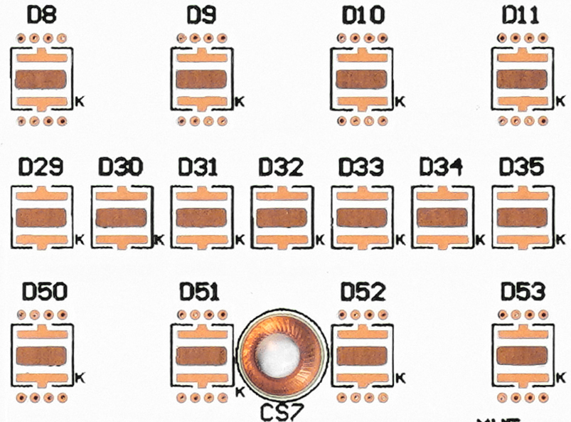
Ø High-Power Components: Effectively prevents overheating in high-power electronic components (such as power amplifiers and LEDs) that need to handle a large amount of heat. For example, in high-power LED products, a thermal and electrical decoupling structure allows heat to be directly transferred through the pad (thermal pad) to the metal substrate, achieving rapid heat dissipation.

What to Consider When Designing Thermal and Electrical Separating Pads?
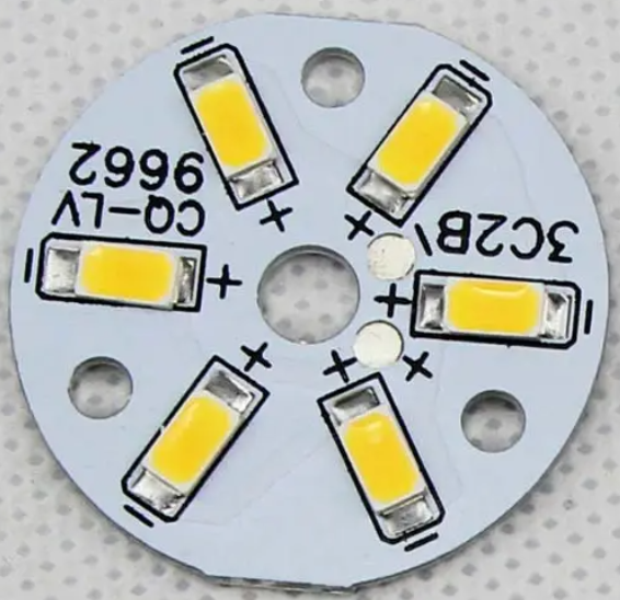
The main two considerations during the thermal and electrical separating pads design are size and solderability. Design pads of appropriate size based on the package size and soldering requirements of the components. An appropriate pad size can ensure a good mechanical connection and electrical contact. For instance, when designing thermal and electrical decoupling pads for LED patches, consider the LED’s package size and the design and marking of the positive and negative terminals.
Another consideration is the soldering reliability. Taking mechanical strength and soldering process of the pads into consideration to ensure the reliability and durability of the solder joints.
How to Correctly Attach an LED to a Thermal and Electrical Decoupling Pad?
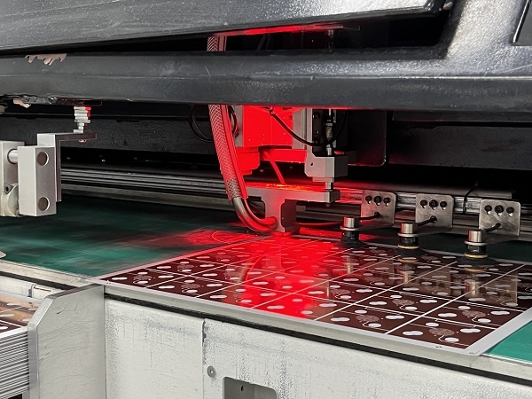
During the manufacturing of the thermoelectric separation MCPCB, one of a key point is to attach the LED chips on the thermal pads correctly. So how to attach and how to make sure its accuracy? Here is a step-by-step process guideline.
1. Review Design Files
a. Check the PCB design drawings and BOM (bill of material) list to identify the positive and negative terminals of the LED and the corresponding pad positions. The design drawings usually indicate the LED’s anode and cathode along with their corresponding pads.

b. Read data sheet as a reference. Review the LED’s specifications or data sheet to understand the pin configuration and polarity markings. The data sheet typically provides detailed information and schematic diagrams of the polarity markings.
2. Check the Polarity Markings on the PCB and LED
Normally, the polarities of LEDs are always present on the PCB. Check the silkscreen carefully on the PCB surface. For example, the positive (anode) pad might be marked with a "+" or "A", while the negative (cathode) pad might be marked with a "-" or "K". Sometimes, a triangle or other symbol might be next to the negative pad.
Additionally, most LEDs have polarity markings as well. For example, the cathode lead of an LED is typically shorter than the anode lead, or there might be a flat side or other marker on one side of the LED package.
3. Double Verification
To ensure correct polarity, employ a double-check method during the assembly process. Arrange an operator places the LED, and another verifies the polarity and position. We saw this method in many factories and our assembly workshop do it too. And before the reflow soldering, perform an initial electrical test to confirm the correct connection of the LED’s positive and negative terminals. Consider to use a multimeter to measure the resistance between the LED and the pads to ensure proper connection.

Final words
By following these steps, you can effectively design and implement thermal and electrical decoupling pads, ensuring both optimal thermal management and reliable electrical performance in electronic devices. Best technology is a metal core PCB supplier, 17 years of dedicating to MCPCB manufacturing, providing metal core circuit board custom design, metal core PCB assembly, prototyping and mass production. You are welcome to contact us if you are interested in the metal core circuit board design and manufacturing.
metal core pcb, led pcb, thermal pad, thermal management,
Related Blog
- What is Thermal and Electrical Separating Pad in Metal Core PCB?
- LED PCB Assembly Process: Step-by-Step Guide for Beginners
- Why Always Recommend White Solder Mask Black Silkscreen for Aluminum PCB?
- What Materials Are Commonly Used for Manufacturing Lighting PCBs?
- Everything You Should Know About Metal Core Circuit Board
- What Are the Differences Between Ceramic PCB, Metal Core PCB And Standard FR4 PCB?
- Why Choose Best Technology As Your MCPCB Manufacturer?
- What is LED Light Circuit Board and How to Make it?
- When is International Labour Day in 2024 and What are the Significances of It?
- How Does A Convexity Comes Out On Thermoelectric Separation Copper Based PCB?
- Why is Aluminum LED PCB Important for Indoor Growth Lights?
- Application of Metal Core Pcbs in the Development of LED Technology
- Why Choose White Solder Mask for Metal core PCB When Used In LED Devices?
- Understanding Aluminum LED PCBs in 1000w LED Grow Lights
- What Are the Advantages of Metal Core PCB? How to Choose?
- Automotive Light Copper Core Pcb Production Process—testing
- Why Are Metal Core PCBs, Especially Copper Core, Used In Heat-Sensitive Electronics?
- How do aluminum LED PCBs improve LED efficiency?
- What Are the Differences Between Regular and Thermoelectric Separation Copper-Base PCBs?
- Aluminum PCB VS FR-4 Performance Comparison


