LED PCB Assembly Process: Step-by-Step Guide for Beginners
- Views
- 08 Jun 2024
- What is a LED PCB?
- Why is LED PCB assembly important?
- Basic tools and materials for LED PCB assembly
- LED PCB assembly process step by step
- Common problems and solutions of LED PCB assembly
LED (light emitting diode) technology has an important position in the field of modern lighting and display electronic devices. Whether used for indoor lighting, displays or electronics, its efficient, low-power property makes them an ideal choice. LED PCB (printed circuit board) assembly is a key step to ensure the performance and reliability of LED equipment. This article will introduce the details of LED PCB assembly step by step for beginners and analyze the potential risk that may result a defective LED PCB, hope this can help you better understand the process.
What is a LED PCB?
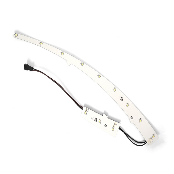
LED is a kind of light-emitting diode. It is a moisture heat sensitive element sealed in a packaging adhesive (silicone or epoxy resin). The LED has a bare piece, phosphor and solid adhesive inside (except for lead bonded COB LED). And LED PCB is a printed circuit board specially used for mounting and driving LED lights. They enable LED chips to emit light by providing electrical connections and mechanical support. Typical LED PCBs use aluminum or copper substrates because they have good thermal conductivity and can effectively dissipate heat.

Why is LED PCB assembly important?
As we know, the quality is the core of an electronic device. And the quality of LED PCB assembly directly affects the performance and life of LED lamps. A good assembly process ensures that LED luminaires are stable, long lifespan, and provide a consistent light output. On the contrary, poor assembly can lead to overheating, uneven brightness and even early failure of the lamp. Therefore, mastering the correct assembly technology is crucial to the production of high-quality LED products.
Basic tools and materials for LED PCB assembly
Before starting assembly, the following tools and materials need to be prepared:
l Tools: Soldering iron, solder wire, tweezers, wire cutters, heat gun
l Materials: LED chips, metal core PCB (aluminum PCB or copper PCB, let’s take aluminum PCB as an example), solder paste, soldering fixture, stencil (for mass production)
LED PCB assembly process step by step
The LED PCB assembly process involves several key steps, including design, mounting, welding, testing and final assembly. Here let us explain it in step by step.
Step 1: Design and prepare the PCB
1. PCB design
When the design files are prepared and finished, using PCB design software (such as CAM350, DWG or others) to create the layout of the LED PCB and determine the location of the LED pads and other components.
2. Making PCB
Send the design files to the manufacturer to produce the aluminum base PCB once the layout and schematic has been completed.
Step 2: Mount the LED chip
1. Solder paste printing
If you mount the LED in your home, then directly apply the solder paste onto the corresponding position of the LED pads. Please make sure the solder paste on all the pads are uniform and enough, don’t make it too much or less. Much solder paste will overflow and insufficient will lead to a poor soldering. Well, if it is a mass orders in your company, then customize a stencil according to the PCB pad layout. And then apply the solder paste on the LED pads through this stencil by a printing machine.
2. Place the LED and other components
Use an automatic placement machine or manual tweezers to accurately place the LED chip and other components on the solder paste. Make sure the positive and negative electrodes of the LED chip are aligned with the pads on the PCB.
Step 3: Reflow welding
1. Preheat the PCB
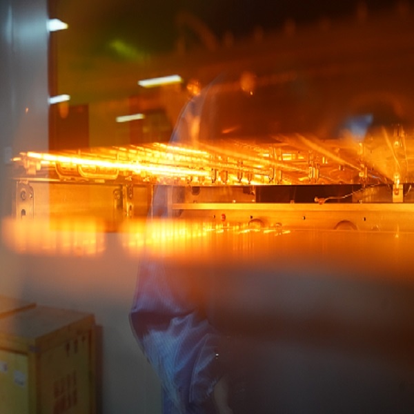
In a reflow furnace, the PCB is first heated to the preheat temperature of the solder paste (usually between 150°C and 180°C).
2. Welding
The PCB continues to be heated to the melting temperature of the solder paste (approximately 240°C to 260°C), so that the solder paste melts and forms a strong weld point.
3. Cooling
After welding, let the PCB cool to room temperature, and the solder joint will cure. Generally, these three steps can be auto-finished by the reflow oven, and what we need to do is setting the oven parameters.

4. Plug-in Assembly
Some components that require higher mechanical strength or current carrying capacity may need to be welded by means of through-hole technology (THT). The process involves inserting components manually or automatically and then securing them by wave soldering or hand welding.
Step 4: Inspection and test
After the assembly is completed, the LED PCB needs to be strictly inspected and tested to ensure that its function and performance meet the requirements. This process includes:
l Visual inspection
Use a magnifying glass or AOI (Automatic Optical Inspection) device to check that each solder joint is in good condition and ensure that there are no soldering defects such as solder balls, Bridges, etc.
l Electrical test
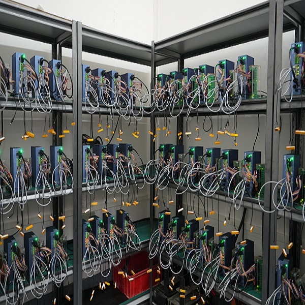
Use a multimeter or special test equipment to check the electrical connection of the LED light and ensure that all LED chips are properly lit.
l Final inspection (FQC & QA)
Functional test of the entire LED luminaires, including brightness, color consistency, temperature rise, etc., to ensure that all performance indicators meet the requirements.

Step 5: Clean and package
Finally, use special cleaning equipment (such as dry ice cleaning) or solvents to clean the LED PCB, remove the residual flux and welding slag during the welding process, ensure that the cleaned PCB is dry, no moisture residue, and then packaging and identification.
Common problems and solutions of LED PCB assembly
After the assembly of the LED PCB, it is possible that some LEDs are not bright or the light emitted by the LED has serious color difference. LED lights may also have premature light decay in use. You can find out why in the LED PCB design and assembly process.
Here are some common problems that our customers ever faced and solutions for your reference:
1. Bad solder joints
Poor solder joints can lead to unreliable electrical connections. Solutions include adjusting the welding temperature, applying the appropriate amount of solder paste, and ensuring that the components are positioned correctly.
2. The LED is off
The LED may not light up due to circuit connection problems or damage to the LED itself. Electrical testing is required to check the circuit and replace the damaged LED.
3. PCB warping
PCB warping may affect assembly and use. The appropriate PCB material should be selected, and the temperature of reflow welding and wave soldering should be controlled.
LED PCB assembly is a complex and delicate process including multiple steps and details. With this step-by-step guide, beginners can better understand and master the key points during SMT process. Best Technology is committed to providing customers with one-stop high quality LED PCB assembly services to help your project succeed. If you have any questions or need further assistance, please feel free to contact our team.
led pcb assembly, led pcb, SMT, led pcb circuit board,
Related Blog
- What is Thermal and Electrical Separating Pad in Metal Core PCB?
- LED PCB Assembly Process: Step-by-Step Guide for Beginners
- Why Always Recommend White Solder Mask Black Silkscreen for Aluminum PCB?
- What Materials Are Commonly Used for Manufacturing Lighting PCBs?
- Everything You Should Know About Metal Core Circuit Board
- What Are the Differences Between Ceramic PCB, Metal Core PCB And Standard FR4 PCB?
- Why Choose Best Technology As Your MCPCB Manufacturer?
- What is LED Light Circuit Board and How to Make it?
- When is International Labour Day in 2024 and What are the Significances of It?
- How Does A Convexity Comes Out On Thermoelectric Separation Copper Based PCB?
- Why is Aluminum LED PCB Important for Indoor Growth Lights?
- Application of Metal Core Pcbs in the Development of LED Technology
- Why Choose White Solder Mask for Metal core PCB When Used In LED Devices?
- Understanding Aluminum LED PCBs in 1000w LED Grow Lights
- What Are the Advantages of Metal Core PCB? How to Choose?
- Automotive Light Copper Core Pcb Production Process—testing
- Why Are Metal Core PCBs, Especially Copper Core, Used In Heat-Sensitive Electronics?
- How do aluminum LED PCBs improve LED efficiency?
- What Are the Differences Between Regular and Thermoelectric Separation Copper-Base PCBs?
- Aluminum PCB VS FR-4 Performance Comparison


