What is LED Light Circuit Board and How to Make it?
- Views
- 03 May 2024
- Understanding What is A LED Light Circuit Board?
- What are the Advantages of LED Light PCB?
- Why Choose Aluminum LED PCB Instead of FR4 LED PCB?
- Why Choose Best Technology as Your LED PCB Supplier?
LED circuit board is a very important electronic component in electronic industry, it is widely used in lighting systems, electronic devices, communication equipment and other fields. Its main role is to connect the LED chip with the circuit board, so that the LED chip can work normally. In this article, we will introduce the advantages and production process of LED circuit board in detail to help you better understand this important element.
Understanding What is A LED Light Circuit Board?
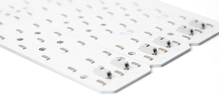
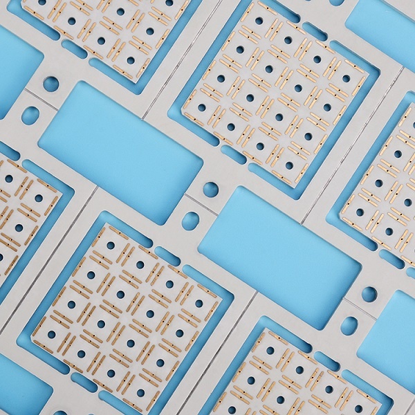
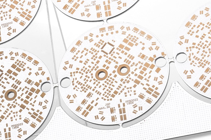
An LED light circuit board is specifically engineered to mount and connect LEDs, optimizing their performance and lifespan. Unlike standard PCBs, LED PCBs are constructed with a focus on superior heat dissipation and electrical layout to accommodate the unique needs of LED technology. Typically made with materials that enhance heat dissipation, these PCBs are critical in preventing heat-induced LED failure, thereby extending the operational life of the lighting system.
LED circuit boards are usually composed of two parts: the circuit board and LED chip. A circuit board is a basic material used to connect electronic components, and it is usually made of metal materials such as aluminum or copper alloy. The LED chip is a semiconductor component, which can convert electrical energy into light energy to achieve lighting functions.

What are the Advantages of LED Light PCB?
LED circuit boards are applied to various applications like lighting systems, electronic equipment, communication equipment and etc. In the lighting system, the LED circuit board can connect the LED chip with the power supply to achieve efficient and energy-saving lighting effects. In electronic devices, LED circuit boards can connect various components to achieve various functions of electronic devices. In the communication equipment, the LED circuit board can connect the communication chip with the power supply to realize the communication function. Below are some common benefits when using LED light circuit board in electronic devices:
l Efficient energy usage
LED PCBs maximize the energy efficiency of light fixtures by reducing heat loss and improving electrical conductivity, which in turn conserves energy and decreases utility costs.
l Increase lifespan
Due to their effective heat management, this kind of lighting circuit boards ensure that LEDs operate within optimal temperature ranges, significantly enhance their lifespan compared to traditional lighting solutions.
l Compact and flexible design
The small size of LEDs and the versatility of PCB materials allow for compact and flexible designs, enabling their use in a variety of modern and space-constrained applications.
l No RF emission release
Another important advantage of using LED PCBs is that they do not emit RF waves during operation. If RF waves are emitted from the device, they will interfere with other electronic devices and components present in the environment. Using an LED PCB will save you from having to worry about RF interference.

Why Choose Aluminum LED PCB Instead of FR4 LED PCB?
Actually, FR4 material can be made into a lighting PCB and it has 0.3W/m.k thermal conductivity, but with the power increasing and rapid development of electronics, fiber glass material cannot meet the thermal management requirements of high-power devices. Additionally, aluminum LED PCB offers numerous advantages that FR4 material cannot provide, including:
1. Excellent durability
Aluminum is more hardness and offers greater mechanical stability under harsh conditions, making it suitable for industrial and outdoor lighting applications where reliability is critical.
2. Lightweight
Another advantage is its light weight properties. Compared with copper or iron material, aluminum remains lightweight, which is beneficial in applications where heavy components are impractical.
3. Cost efficiency
Given its durability and thermal benefits, aluminum can offer a better long-term investment and environment friendly, reducing maintenance and replacement costs.

How to Make a LED Lighting Circuit Board Step by Step?
Creating your own LED PCB board can be an exciting and rewarding project. Here’s a step-by-step guide to help you get started:
Step 1: Designing the Circuit – Firstly, when you have an idea about your PCB, then you can start with the layout drawing. Confirm with precise specifications for the LED application, including the number of LEDs, their configuration, and power requirements. Use computer-aided design (CAD) software or CAM350 to create the schematic and layout. Please be noted: it is necessary to take into account the voltage, current and power of the LED chip to ensure the stability and reliability of the circuit during the design process.
Step 2: Selecting Appropriate Substrate – Both aluminum and copper are good materials for creating LED lighting circuit board. Choose appropriate substrate for your project according to your demands. Normally, aluminum is enough to carrier low and middle power lights, but if it requires for higher power and excellent thermal management properties, then copper is a good option. Ensure the thickness and type of substrates are suited to the specific needs of the application.
Step 3: Fabricating the PCB - The process of making a circuit board is divided into two steps: making a printed circuit board and drilling holes. The printed circuit board is print the circuit diagram onto the copper/aluminum sheet, and then the unwanted part is etched by chemical corrosion to form the traces of the circuit board. Drilling is to drill out the parts of the circuit board that need to be inserted so that subsequent parts can be installed. Surface finish and silkscreen are applied to protect the circuit and provide labels.
Step 4: Assembling Components - Mounted LEDs and other components using SMT (surface mounted technology) that ensure strong connections without damaging the LEDs. During the soldering, it is necessary to pay attention to the welding temperature and time to avoid excessive or insufficient welding leading to solder joint fracture.
Step 5: Function Testing - Connect the made LED circuit board to the power supply for testing. Pay more attention to the current and voltage parameters of the circuit to ensure that the LED chip can work normally.
Why Choose Best Technology as Your LED PCB Supplier?
Best Technology excels in LED PCB manufacturing, combining advanced technology, years of experience, and a commitment to quality and delivery. Choosing Best Technology as your LED PCB supplier guarantees a partnership with a leader dedicated to delivering tailored one-stop solutions that illuminate the world of lighting technology. Whether your project is large or small, Best Technology’s commitment to excellence shines as brightly as the solutions it provides.
LED light circuit board, LED pcb, Light pcb, led light pcb,
Related Blog
- What is Thermal and Electrical Separating Pad in Metal Core PCB?
- LED PCB Assembly Process: Step-by-Step Guide for Beginners
- Why Always Recommend White Solder Mask Black Silkscreen for Aluminum PCB?
- What Materials Are Commonly Used for Manufacturing Lighting PCBs?
- Everything You Should Know About Metal Core Circuit Board
- What Are the Differences Between Ceramic PCB, Metal Core PCB And Standard FR4 PCB?
- Why Choose Best Technology As Your MCPCB Manufacturer?
- What is LED Light Circuit Board and How to Make it?
- When is International Labour Day in 2024 and What are the Significances of It?
- How Does A Convexity Comes Out On Thermoelectric Separation Copper Based PCB?
- Why is Aluminum LED PCB Important for Indoor Growth Lights?
- Application of Metal Core Pcbs in the Development of LED Technology
- Why Choose White Solder Mask for Metal core PCB When Used In LED Devices?
- Understanding Aluminum LED PCBs in 1000w LED Grow Lights
- What Are the Advantages of Metal Core PCB? How to Choose?
- Automotive Light Copper Core Pcb Production Process—testing
- Why Are Metal Core PCBs, Especially Copper Core, Used In Heat-Sensitive Electronics?
- How do aluminum LED PCBs improve LED efficiency?
- What Are the Differences Between Regular and Thermoelectric Separation Copper-Base PCBs?
- Aluminum PCB VS FR-4 Performance Comparison


